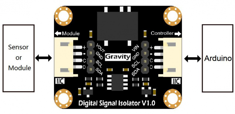
I2C Control Schematicįinally, we have the I2C IO Expander schematic, with a 5v LDO regulator, capable of providing up to 600mA of current to the PCB. The Relay contacts themselves, being magnetically actuated by the coil, are in themselves Galvanically Isolated from the rest of the PCB. Although this arrangement does not provide complete galvanic Isolation of the relay coil, it does protect your MCU from any voltage spikes caused by back-emf when the relay is de-energised. Each relay output is driven through an optocoupler, as well as a transistor. This may still work but renders the galvanic Isolation for that input completely useless. DO NOT connect the PCB Module ground to an isolated ground pin. Please note that you have to supply a remote ground from the device that provides the input. Complete Galvanic Isolation between the Module and the remote input is in effect. Each input operates at a voltage of 5.5v to 32v DC. This is the Galvanic Isolated Input schematic. The Circuit diagram is below, and I will discuss each part briefly. Meaning eight of each variant) This surely adds up to quite a lot of IO lines at a cost of only 2 GPIO on your MCU! The PCB uses the popular PCF8574 8 channel IO expander, which is extremely easy to use, and where you can connect up to 8 devices in a chain ( 16 if you use the PCF8574AT variant as well. If you need to interface to a 3.3v microprocessor, like an ESP32 or ESP8266, or even the new RP2040 or an STM32, you need to use a logic level converter. That includes the I2C data lines (SDA and SCL). The module I am presenting to you today was designed to be operated from 5v DC. I also love using I2C, as it allows me to add modules onto an existing data bus while using only 2 GPIO lines on the MCU!


( Note that the optical isolation voltage does not mean you can input that voltage level into the chip! It means that it can isolate the electronics on the safe side of the isolator from a voltage spike of up to that voltage!). It is thus extremely important to have a module that can effectively interface with inputs of 5.5v up to 32v DC ( optically Isolated up to 3000v ), and relay outputs, also optically isolated at 3000v.

I will also tell you about a very special deal to get PCBs of your own made for only one (1) USD ( Including shipping with DHL )! No, I am not joking, and I am not crazy either… More on that later in the post… To implement it properly we also need a lot of additional electronic components to properly isolate these inputs and outputs, with the signals they switch, from our own project, because, let us be real, electronics and electrical devices in the real world do not all work with Arduino or ESP32/ESP8266 save voltages ( 5v and 3.3v ). Sometimes we need extra Inputs or Outputs on a device, or for use with a project.


 0 kommentar(er)
